
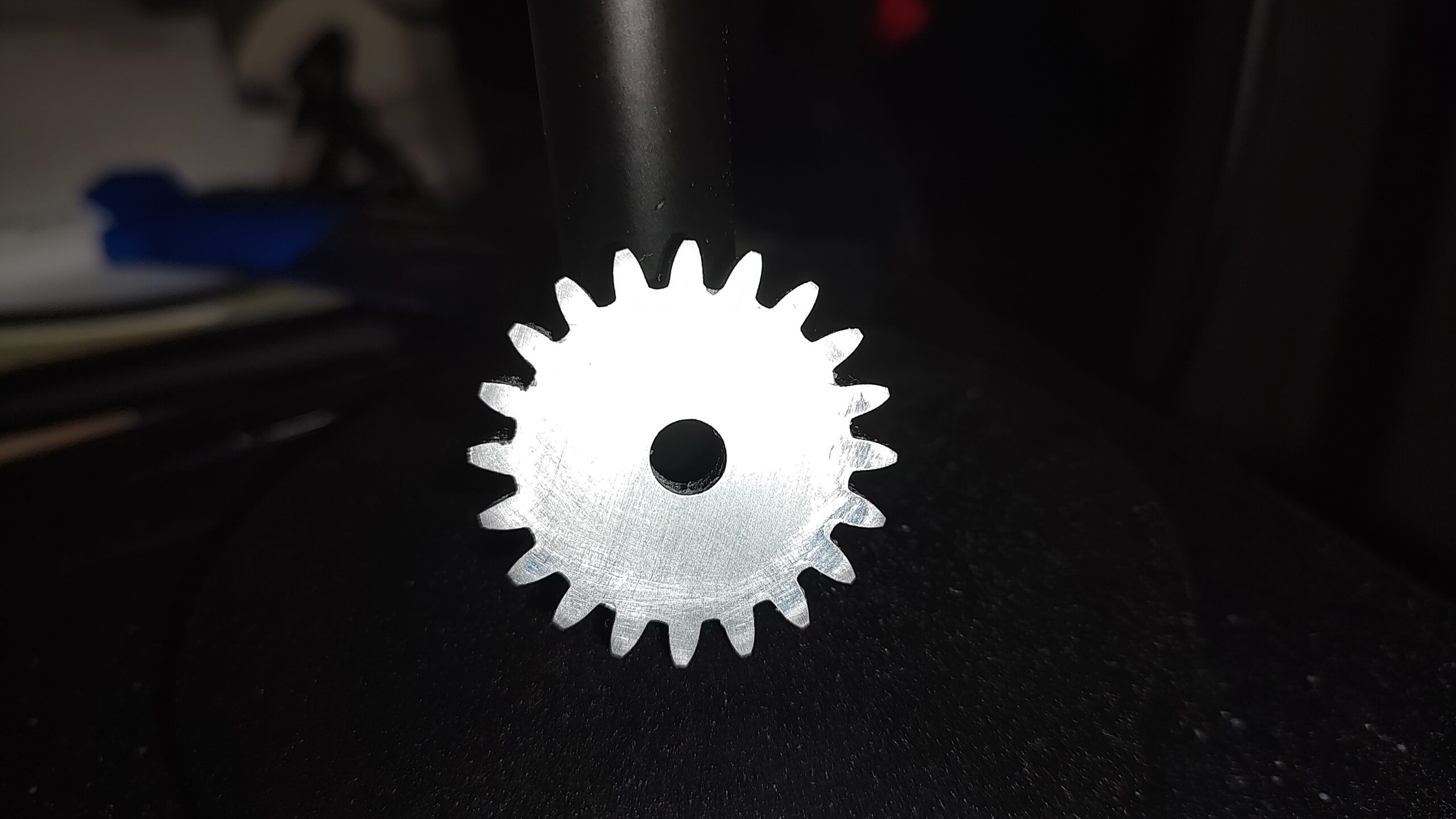
After more than a week, success was had.
The number of subprojects that went into this one simple little gear boggles my mind.
- Locate a reasonable rotary table
- Document what was needed for it
- Clean and restore 8″ Cushman Chuck
- Make chuck key
- Locate dividing plates for the rotary table
- Make T-Nuts for rotary table
- Make socket-head replacement screws for chuck
- Make socket-head attachment screws for chuck/backplate interface
- Make backplate
- Make retaining collar
- Make MT3 alignment plug
- Modify eccentric to have a retaining grove for U-Spring
- Make grooving tool
- Make nose cap for spindle
- Thread eccentric for tensioning ring
- Make a mandrel for holding gear blanks
- Make gear blanks
- Read the section in the 1914 Machinery’s Handbook about gears
- Create Emacs spreadsheet to calculate gear cutting parameters
- Create a Python program to create a dividing plate table
- Incorporate dividing plate information into Org-mode spreadsheet for single point of information (Enter DP and Number of teeth, get out cutting parameters and which dividing plate to use along with dividing plate setup)
In addition to that, I have 3 toolholders almost finished, I’m still waiting for the dovetail cutter to arrive and then to drill and tap the adjustment screw plus the retaining screws.
For those that might wonder why 14.5° PA, 16 DP instead of a more modern 20° PA, it is because this is what my lathe uses. With a single purchase of the 8 involute cutters, I can make any gear my lathe might need.
Awesome! Congrats on getting it done!
Go Go Gadget Gear Head!!
Congrats.
Now, for the induction hardening…. /just kidding…
nice! an interesting (maybe) side note- some of the older paint shakers I have repaired have a fixed nylon gear with an aluminum gear that rotated around it. the aluminum gear would wear out long before the nylon one..
Ah, the eternal game of “tools to make the tools to make parts for the tools that I use to make the….”
Always more steps than you think, and always more skills to pick up along the way.
It’s interesting to see the “bootstrapping” process of creating tools. I have a book that explores some of this from the most basic item: a flat surface. It’s a coffee table book published by Moore Tool Co., “Foundations of mechanical accuracy”. It’s about their precision 3d measuring machines, derived from their “jig grinder” machines, but it starts with making surface plates, then squares, precision angle measurement, and so on. Fascinating stuff.
One of the cool things is that precision measuring starts with being able to make flat surfaces and right angles. IIRC, you start with three surfaces. You can remove high spots with a simple file. To identify a high spot, you ink one surface(a) and rub surface(b) against it. You then file the mark locations down. You repeat with surface(b) v. surface(c). By working all three against one another, you will average the errors.
.
Once you have filed things nearly flat, you switch to scrapping. I’ve scrapped a surface flat. There is something amazing about watching a rough casting transform into something that floats across the surface plate on a layer of air.
.
The same process is used for right angles. By working three angles against each other you end up with a scrapped surface that is perpendicular to your reference surface.
.
That plus using crude screws to make more precision screws to make still more precision screws is cool.
Yes, and the Moore book goes into a lot of those details.
The surface plate bit has a wrinkle I hadn’t seen elsewhere: they point out the importance of using square plates, so you can rotate them 90 degrees and check again. If you use rectangular plates where you can’t rotate 90 and check, you will end up with saddle shapes.
They mention several high precision rotary tables. One is particularly neat because it’s self-adjusting. Imagine two face gears with 360 teeth, cut on a decent machine. Now set one on top of the other so the gears mesh, but with some grinding compound in between. Lift, turn one degree, set down. Repeat for a long time. The result will be that all the position errors in the teeth are ground away.
The machine they were building uses triangular ways (like some lathes do, my Reed-Prentice for example). Getting the full geometry of those correct is tricky and they also show how those gauges are created. I forgot the details.
I’m really enjoying your “adventures” with machining. Especially now that I’ve picked up my own mini lathe and I’m just about ready to start turning on it. Is it just me, or do the teeth on that gear seem to “lean” a little to one side? Maybe it’s just the photo.
I looked and saw the same thing. I made three more gears today in a gang milling setup. The teeth do not lean. The shape of the teeth is not consistent. I will have to figure out what is happening. I am pretty sure has something to do with runout or other issues with my setup.