

I have all the raw materials in hand, as well as the motor and power supply. The 5 mm drive belt material is somewhere in the reloading supplies. It is the material I used to make a replacement belt for the wet tumbler when the original, 20-year-old belt broke.
Is this a commercial design? No. The front drive belt is there to provide a built-in safety. It will slip if there is too much drag on the system. In a finished product, I would be mounting the motor differently, behind the front plate.
In the same way, the idler shoulder bolt would be a blind hole instead of a through hole.
Finally, it is likely that a better design would use belts for driving everything instead of gears and belts.
Here’s a peek at the rear.
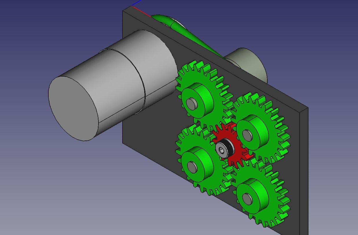
As soon as I get working drawings out of FreeCAD, I’ll go into the shop and make the faceplate and mount up the motor.
The next step will be to press the bearings into the faceplate. Then I’ll make the drive pulley, the cutter/driven pulley, and the three toolholders.
The last step is making the gears. I’ll be cutting a longish piece of Delrin with 22 tooth gears. That long gear will then be cut into 4 actual gears to use. The final task will be the 14 tooth idler gear and the shoulder bolt.
Exciting times.
Maybe an adjustable clutched drive in the gear system instead of a belt? I’m thinking small cases (5.56) would require less energy to process than, say, .375 H&H or .416 Rugby so a way to accommodate the additional force required might be worthwhile, and “adjustable” allows for compensating for wear. Not as simple to make, or maintain, however, but someone must have some sort of “canned clutch drive” in a piece of equipment, somewhere (and, yes, I have a preference for “drop-in, shrink-wrapped solutions” 0f all types).
What does it do?
(Probably answered in prior reloading posts I haven’t read yet).
There are four turning shafts. The one with the large threaded hole will accept a standard case trimmer cutter. Those case trimmer cutters have a hole that accepts guides for aligning the case with the cutter, Lyman makes a version of those guides that have a stop that allows you to cut the case to a single fixed length.
.
The smaller threaded holds take standard #8-32 tools, such as case mouth chamfer tools and pocket cleaning/reaming tools
Oh very handy!
So it’s somewhat similar to this guy:
https://www.frankfordarsenal.com/case-preparation/case-trimming/platinum-series-case-trim-and-prep-center/903156.html
I’ve had one of these for a couple of years now, It’s not a perfect tool, but it’s functional. My rifle reloading is very low volume, so it doesn’t get a lot of use. The cutter on this tool is slow. I’ve heard some recommend you can upgrade to an RCBS carbide cutting head that works better.
That is one of the gizmos I noticed that lead me to this design. I did read that people were concerned about the speed of the spindle. Here are the actual numbers:
.
Brass: Surface feet Per Minute is 100-200.
Cutter Diameter: 0.250-0.500 which gives us 0.065446-0.130893 ft/rev.
This gives us a target spindle speed of 1500-775 RPM.
For me, I would rather not stick my fingers near any cutter spinning at 1500RPM. My design puts the spindle speed at 300RPM. This is slow but safer, I hope.
Mscdirect.com is your friend. Those size gears should be available. 3 or 4 bucks a piece.
I have an account with them from before the merger. I even get a discount. I looked into purchasing the gears but there is more to this.
.
I happen to have a complete set of DP16 PA14.5 cutters. My South Bend lathe uses a DP16, PA14.5 gear train. There are more than a couple of gears that I want for the machine that are north of $100 each. If I can learn to cut gears correctly, My life gets better.
.
The magic is the DRO for the mill. I believe the target gear is 121 teeth. This is not something most dividing head plates can do. Prime numbers and all that. But, I can make a plate that will fit the dividing head and then use the mill and DRO to make a custom dividing plate to cut that gear.
Those gears look like a perfect application for a 3d printer…
They could be, if my 3D printer was up and running and tuned correctly.
.
More important to me, is that I want to cut gears. It is one of the “difficult” things a machinist does. I have a rotary table and a set of 14.5 deg 16DP cutters. This should be fun.
Nice. And yes, that’s a fun machining challenge. For me the hardest thing I have done is cutting metric thread on an inch lathe.
Re cutting slowly: I like that approach too. I’m pretty sure I can run my lathe at speeds far higher than what I normally use, but I’m not in a hurry. And my plexiglas chip shield doesn’t like it when the chips are hot, they embed in the plastic… as I found out when refinishing the faceplate (10 inches or so diameter, so it doesn’t take high RPMs to get hot chips).
You sir have much more skills than I do.
I can do woodwork , having grown up using my fathers Shopsmith and surviving with all 10 fingers, but metal work with a lathe is beyond me.
Following this story closely…